
TDA2030 Amplifier
+5
arkin
longthrow
weak_man23
MCU
Hertz
9 posters
Page 1 of 1
![]()
 TDA2030 Amplifier
![]() by Hertz Wed Sep 07, 2011 10:28 am
by Hertz Wed Sep 07, 2011 10:28 am
post natin ang mga amplifier na gamit ang tda2030a
TDA2030 Amp OTL 15W

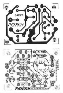
source: http://electronics-diy.com
_________________
3rd member of STTM
former 4th member

Hertz- Admin

- Posts : 1822
Join date : 2010-08-12
Age : 43
Location : Cagayan De Oro City
![]()
![]()
Re: TDA2030 Amplifier
![]() by MCU Fri Sep 23, 2011 12:30 pm
by MCU Fri Sep 23, 2011 12:30 pm
2 channel Hi-fi Amp using tda2030a


◆ PCB printed circuit board size: 88 * 73 * 1.6mm; refined overall height: 32mm.
◆ Output power: Speaker impedance 8Ω � 12V voltage output power of about 15Wx2.
◆ voltage range � 6 - � 22V
▲ circuit features:
[1] very few external components.
[2], output power, Po = 18W (RL = 4Ω).
[3] with ultra-small package (TO-220), can increase the packing density.
[4] turn impact is minimal.
[5] containing various protection circuits, so safe and reliable. The main protection circuit: short circuit protection, thermal protection, accidental open ground, reverse polarity (Vsmax = 12V) and load discharge voltage recoil and so on.
[6] TDA2030A � 6V maximum in the minimum voltage of � 22V to work in the � 19V, 8Ω impedance to the effective power output of 16W, THD ≤ 0.1%. No doubt, use it for computer power amplification part of the active speaker or a small amplifier appropriate.
* Model: HIFI power amplifier TDA2030A
* Manufactured by: - Hiendking -
2 Channel Hi-Fi AMp
Source: hiendking.com/hifi-power-amplifier-tda2030a-amplifier-board-spare-parts-kit-p-3459.html

MCU- Admin
- Posts : 115
Join date : 2010-08-11
Age : 48
Location : Tagum City -

![]()
![]()
Re: TDA2030 Amplifier
![]() by weak_man23 Fri Dec 30, 2011 4:26 pm
by weak_man23 Fri Dec 30, 2011 4:26 pm
tol. pwede pa hingi nang component partlist:

weak_man23- AAA Battery

- Posts : 1
Join date : 2011-12-30
![]()
![]()
Re: TDA2030 Amplifier
![]() by longthrow Tue Jan 10, 2012 1:24 pm
by longthrow Tue Jan 10, 2012 1:24 pm
use tda 2050 for better performance
better sounding than 2030 @ almost same price
also, rated 32w & can be powered +/- 20v
using same ckt as 2030.
better sounding than 2030 @ almost same price
also, rated 32w & can be powered +/- 20v
using same ckt as 2030.

longthrow- AAA Battery
- Posts : 37
Join date : 2012-01-10
Age : 44
Location : cebu
![]()
![]()
Re: TDA2030 Amplifier
![]() by arkin Wed Jan 11, 2012 9:32 pm
by arkin Wed Jan 11, 2012 9:32 pm
agree!2050-32w,can run at higher voltage.2030-14w,same pentawatt package,same pin connection.
arkin- D Battery

- Posts : 446
Join date : 2011-12-02
![]()
![]()
Re: TDA2030 Amplifier
![]() by ultrasonic™ Thu Jul 05, 2012 2:01 pm
by ultrasonic™ Thu Jul 05, 2012 2:01 pm
my ganito palang thread
eto galing pang elab
AUDIO AMPLIFIER TDA2030 2 + 1 CHANNEL
This project is Power Audio Amplifier with TDA2030 2.1 Chanell – 3 x 18 Watts – Subwoofer – Complete With PCB suggestion and power supply.

This circuit is a complete application is 2.1 amp, two satellite speakers for TDA and one for the subwoofer, making the 2.1 system, widely used in commercial applications as an amplifier for computers, which may give an increased in its audio system with a stereo amplifier bass amplifier (subwoofer).
Description of the amplifier circuit with TDA 2030
The circuit is divided into 3 parts: power supply, amplifier, stereo amplifier and bass amplifier (subwoofer).
TDA2030 2.1 – Schematic of the power amplifier


Power supply circuit and pre low pass filter for the sub power supply
The power supply is of symmetric type, using a transformer, 110 or 220 with dual secondary 12 volts and 3A current. I recommend using a fuse and a switch before the transformer. B1 is a bridge rectifier least 100 volts / 4 A, an example that can be used is GBU606, the filtering circuit is formed of the capacitors C1, C2, C3 and C4, the electrolytes can have values from 4700μF . The power supply for the op amp Highpass filter, is used three terminal integrated circuits 7812 and 7912.


Circuit of the amplifiers of satellite speakers
The left and right channels give exactly the same, let’s see how the left channel: LIN is the audio input jack, which is coupled by C20 to the pot volume adjustment, it is a double pot, and set the two channels simultaneously. R19/C22, helps to improve the signal of the treble. The capacitor C21 couples the signal to CI6 TDA2030, after amplified audio output is pin 4 of integrated. The resistor R7 and R9 are responsible for feedback, so by changing the value of R7 can increase or decrease the gain of the amplifier. R20 and C23 form the compensation network for the speakers.
Circuit pre and Amplifier Subwoofer
The signal comes from the subwoofer to the left and right channels by resistors R15 and R10 being decoupled by capacitor C12, is applied in the operational amplifier 1 IC4A NE5532, which forms a pre-amplifier to boost the signal by 6 times. Determined by R6/R8 resistor.
The components C9, C10 and R10 form a low pass filter in this case is calculated to 200Hz. After leaving IC4B the low frequency audio through the potentiometer P1 that makes the volume level, then forwarded to IC3 is what makes the subwoofer amplifier, the operating principle is the same as satellite amplifiers.
Suggested PCB for the circuit of the amplifier


source: http://electronica.otg.mk/all_articles/Audio_Accessories/Amplifier_with_TDA2030_2 1_Chanell/TDA2030.html
eto galing pang elab
AUDIO AMPLIFIER TDA2030 2 + 1 CHANNEL
This project is Power Audio Amplifier with TDA2030 2.1 Chanell – 3 x 18 Watts – Subwoofer – Complete With PCB suggestion and power supply.
This circuit is a complete application is 2.1 amp, two satellite speakers for TDA and one for the subwoofer, making the 2.1 system, widely used in commercial applications as an amplifier for computers, which may give an increased in its audio system with a stereo amplifier bass amplifier (subwoofer).
Description of the amplifier circuit with TDA 2030
The circuit is divided into 3 parts: power supply, amplifier, stereo amplifier and bass amplifier (subwoofer).
TDA2030 2.1 – Schematic of the power amplifier
Power supply circuit and pre low pass filter for the sub power supply
The power supply is of symmetric type, using a transformer, 110 or 220 with dual secondary 12 volts and 3A current. I recommend using a fuse and a switch before the transformer. B1 is a bridge rectifier least 100 volts / 4 A, an example that can be used is GBU606, the filtering circuit is formed of the capacitors C1, C2, C3 and C4, the electrolytes can have values from 4700μF . The power supply for the op amp Highpass filter, is used three terminal integrated circuits 7812 and 7912.
Circuit of the amplifiers of satellite speakers
The left and right channels give exactly the same, let’s see how the left channel: LIN is the audio input jack, which is coupled by C20 to the pot volume adjustment, it is a double pot, and set the two channels simultaneously. R19/C22, helps to improve the signal of the treble. The capacitor C21 couples the signal to CI6 TDA2030, after amplified audio output is pin 4 of integrated. The resistor R7 and R9 are responsible for feedback, so by changing the value of R7 can increase or decrease the gain of the amplifier. R20 and C23 form the compensation network for the speakers.
Circuit pre and Amplifier Subwoofer
The signal comes from the subwoofer to the left and right channels by resistors R15 and R10 being decoupled by capacitor C12, is applied in the operational amplifier 1 IC4A NE5532, which forms a pre-amplifier to boost the signal by 6 times. Determined by R6/R8 resistor.
The components C9, C10 and R10 form a low pass filter in this case is calculated to 200Hz. After leaving IC4B the low frequency audio through the potentiometer P1 that makes the volume level, then forwarded to IC3 is what makes the subwoofer amplifier, the operating principle is the same as satellite amplifiers.
Suggested PCB for the circuit of the amplifier
source: http://electronica.otg.mk/all_articles/Audio_Accessories/Amplifier_with_TDA2030_2 1_Chanell/TDA2030.html
_________________
6th member of STTM
former 2nd member
im always walking on the rain so that no one could see me crying

ultrasonic™- 24V BATTERY

- Posts : 4475
Join date : 2010-08-19
Age : 38
Location : Davao City
![]()
![]()
Re: TDA2030 Amplifier
![]() by Deep Bass Fri Jan 11, 2013 2:37 pm
by Deep Bass Fri Jan 11, 2013 2:37 pm
yang pinost ni sir ultra yan yung ginamit ko pang drive sa amp booster but wala lang to NE5532 ang ako nakit an kay TL084N ok pud kau boomy pud
Deep Bass- AA Battery

- Posts : 53
Join date : 2012-12-23
![]()
![]()
Re: TDA2030 Amplifier
![]() by DJFEL Fri Jan 25, 2013 5:23 pm
by DJFEL Fri Jan 25, 2013 5:23 pm
nice one...abang ako sa sosonod na kabanata neto..

DJFEL- 24V BATTERY
- Posts : 1780
Join date : 2012-11-21
Age : 42
Location : SIUIJOR
![]()
![]()
Re: TDA2030 Amplifier
![]() by pyroelectro Sat Jan 26, 2013 12:09 pm
by pyroelectro Sat Jan 26, 2013 12:09 pm
aba laganap iyang tda2030 sa mga china made na 2.1 at 5.1 channel

pyroelectro- C Battery

- Posts : 288
Join date : 2010-11-23
Age : 40
Location : Cebu City
![]()
![]()
![]()
» 40W Power Amplifier
» Subwoofer Amplifier
» WESTRAK amplifier
» audioline v12 car amplifier
» Kenwood amplifier
» Subwoofer Amplifier
» WESTRAK amplifier
» audioline v12 car amplifier
» Kenwood amplifier
Page 1 of 1
Permissions in this forum:
You cannot reply to topics in this forum|
|
|