
3 Way Active Crossover (From Siliconchip)
5 posters
Page 1 of 1
![]()
 3 Way Active Crossover (From Siliconchip)
![]() by Hertz Thu Aug 15, 2013 3:17 pm
by Hertz Thu Aug 15, 2013 3:17 pm

Active 3-Way Crossover for Loud Speaker Systems
Get the very best from your 3-way loudspeaker system with this easy-to-build high-performance design.
Design by Mick Gergos
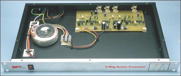
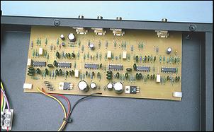
The shot inside the box reveals the simplicity of construction. Everything except the transformer is one one PC Board!
What is an active crossover and why would you want one?
Most hifi enthusiasts are aware that 2-way and 3-way loudspeaker systems contain passive networks to split up the audio spectrum into two frequency bands in the case of 2-way systems and three bands in the case of 3-way systems.
Passive crossover networks use inductors, capacitors and resistors to split the audio into the various bands and set the signal levels to the various speaker drivers.
For example, the woofer is often less sensitive than the midrange driver and tweeter and so the signals to the latter drivers have to be reduced so that the overall output from the three drivers is equal.
Features
|
They also interpose a complex network between the speakers and the amplifier which means a loss of damping factor, particularly for the lower frequencies where it is most needed, if you are to achieve tight, clean bass and midrange reproduction.

Fig.1: the block diagram shows the overall system layout. It replaces the crossover currently in the speaker enclosure.
OK, so that's the passive approach. It involves just one stereo amplifier to drive the two speaker boxes in a stereo system.
In an "active" system, we eliminate the passive crossover networks and electronically split each of left and right channel signals into three frequency bands: low, midrange and high. This is the job of the "active crossover".
Its output signals are fed to six (yep, six) separate amplifiers to drive the woofer, midrange and tweeter units in each loudspeaker enclosure. The overall system layout is shown in the block diagram of Fig.1.
So you end up with a lot more amplifiers than in a conventional system but it gives you a lot more flexibility. And ultimately, you can end up with a system with higher performance, including much higher power levels.
The active crossover approach also means you can mix 4Ω and 8Ω drivers in the same system and match the levels easily, without power wastage.
Active crossover
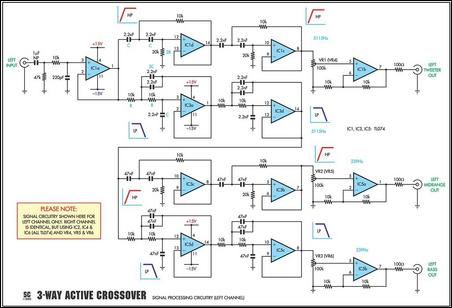
Fig.2: just 12 op amps and a few other components make up each channel of the active crossover. The six outputs (three only shown here; three more in the right channel) each drive separate power amplifiers for the tweeter, midrange and bass drivers in your loudspeakers.
The Active Crossover presented here is housed in a 1-unit high rack case with just the power switch on the front panel.
There are no user controls for the crossover; no switches to alter the crossover frequencies nor external level controls for the output signals. To alter the drive to the loudspeakers, you will need to adjust the volume controls of the driver amplifiers.
On the rear panel there are four pairs of RCA sockets, one pair for the stereo input signals while the other three are for the stereo low (woofer), midrange and high (tweeter) signals.
Also on the rear panel is the IEC mains power socket and a fuseholder for the primary circuit of the power transformer.
Inside the case, all the circuitry is on a PC board measuring 219 x 99mm and this includes the dual RCA input and output sockets. The only external wiring to the board are the secondary connections to the toroidal power transformer.
Circuit description
Now let's have a look at the circuit of Fig.2. Since both channels are identical, this shows only the left channel. While the power supply is also on the PC board, it is shown in Fig.3.
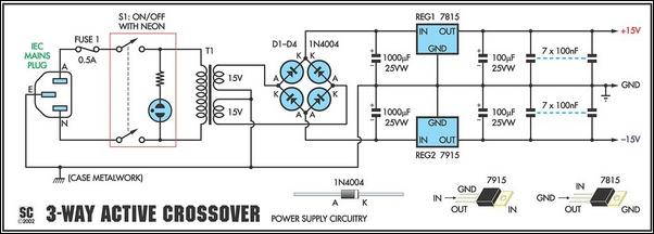
Fig.3: the power supply is entirely conventional, using positive and negative 15V regulators to give ±15V rails. Everything from the bridge on is mounted on the PC board. The seven 100nF capacitors are bypasses distributed around the PC board.
In total, the left channel uses 12 op amps, in three TL074 quad FET-input op amp packages.
Four op amps, IC1a, IC1b, IC5a & IC5b, act as input or output buffers while the remaining eight op amps are Linkwitz-Riley active filter stages with 12dB/octave filter slopes.
In each case, two 12dB/octave filters are cascaded to give an overall filter slope of 24dB/octave. This is far steeper than is normally used in passive crossover networks.
The voltage gain of all these filter stages in the passband is unity.
Low pass, high pass
Before we go any further we should explain some terms which often confuse beginners: low pass, high pass and bandpass.
A low pass filter is one that allows low frequencies to pass through and it blocks the higher frequencies. Hence, a circuit to drive a subwoofer would be called a low pass filter since it only delivers frequencies below 200Hz or thereabouts.

Fig.4: the basic arrangements for the low pass and high pass filters.
Similarly, a high pass filter is one that allows high frequencies to pass through and it blocks low frequencies. Hence, the part of a crossover network which feeds a tweeter is said to be a high pass filter, even though it may consist of only one capacitor.
If we cascade (ie, connect in series) a high pass filter with a low pass filter, the combination will pass a band of frequencies and we then refer to it as a bandpass filter. We use a band-pass filter for the midrange output in this active crossover circuit.
The other points you need to know about high and low pass filters are the so-called cut-off frequency and the filter slope.
The filters used in this circuit have an attenuation of 12dB/octave; this is the filter slope and it applies for frequencies after the cut-off frequency. The cut-off frequency is where the signal output is -3dB down on the normal level.
For example, in a low pass filter we might have a cut-off frequency of 1kHz (ie, -3dB point) and from there on the filter slope could be 12dB/octave. In theory, this means that the response at 2kHz (ie, one octave above 1kHz) will be -15dB although in practice it might not be quite that good.
The filters used in our circuit are of the Linkwitz-Riley configuration and we use eight of these filters, four high pass and four low pass, in each channel. Each filter consists of an op amp connected as a voltage follower, preceded by two RC networks.

Fig.5: this graph shows the three filter response curves which were plotted separately. The overall response curve at top (red) was plotted using the mixer circuit in Fig.8. The overall response curve is extremely smooth.
As already noted,for each high pass and low pass filter we are using two 12dB/octave filters cascaded, to make the total roll off 24dB/octave (4th order) per filter stage.
The basic filter configurations are shown in Fig.4, together with the formula for calculating the crossover frequency. In this particular case, the crossover frequency is at the -6dB point and the reason for this is that we are cascading two filters for each section (2 x 3dB = 6dB).
Note that the capacitors in the low pass filter are shown with values of C and 2C while in the high filter we have resistors with values of R and 2R.
In the main circuit of Fig.2 you will note two capacitors of equal values have been used for the 2C component, as it is difficult to obtain capacitor values exactly double that of another. On the other hand, resistors are much easier and so we have values of 10kΩ for R and 20kΩ for 2R.
Now after that little diversion, let's refer back to the circuit of Fig.2.
The input to the left channel is fed via an RC filter, to roll off frequencies above 100kHz, and then to op amp IC1a which is connected as a unity gain buffer (or voltage follower).
It drives two high pass filter stages associated with IC1d & IC1c, and two low pass filters associated with IC3a & IC3d. Both these low pass and high pass filters have cutoff frequencies set to 5.1kHz.
The output of the second high pass filter, IC1c, is fed to the level setting trimpot VR1 and then to op amp IC1b which is connected as a non-inverting amplifier with a gain of two. It drives the left treble output (tweeter). Hence the tweeter only gets frequencies above 5kHz.
Midrange band-pass

Fig.6: the component overlay, as viewed from above the PC board. Note the polarity of electrolytic capacitors and ICs when soldering them in!
The output of low pass filter IC3d feeds high pass filters based on IC3c & IC3b, both with cut-off frequencies of 239Hz. The output of high pass filter, IC3b, is fed to trimpot VR2 and then to op amp IC5a which has a gain of two.
This drives the left midrange output which gets the band of frequencies between 239Hz and 5.1kHz.
As well as driving high pass filters IC3c & IC3b, op amp IC3d also drives the cascaded low pass filters based on IC5d & IC5c, again with a cut-off frequency of 239Hz. IC5c drives trimpot VR3 and then op amp IC5b which has a gain of two. It drives the left bass output which only gets signals below 239Hz.
All the outputs from each stage are in phase at the crossover points. Voltage gain at the crossover frequency for each section is -6dB (ie, half the reference level).
Thus when the response curves of all three sections are added together, the result is an extremely flat frequency response with an overall gain of unity.
Just how well this works is shown in the response curves of Fig.5. We've plotted the three filter responses and then the resultant curve is plotted along the top. The adder circuit we used to do this is shown (for interest only) at the end of this article in Fig.8.
Power supply
The power supply circuit is shown in Fig.3. It uses a 20VA toroidal power transformer with two 15V secondaries driving a bridge rectifier (diodes D1 - D4) and two 1000μF 25V capacitors to derive unregulated DC supplies of around +-22V DC. These are fed to 3-terminal regulators REG1 and REG2 to produce supplies of ±15V DC. These are each bypassed by a 100μF 25V capacitor and seven 100nF multi-layer ceramic capacitors distributed around the PC board.
Construction
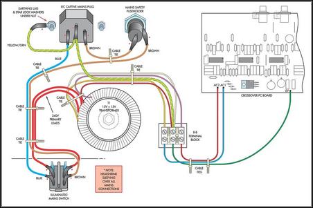
Fig.7: follow this wiring diagram and you should have no problems with final assembly. Be especially careful with the mains wiring - note the heatshrink covering all the "bitey" bits!
As already noted, all the circuitry is on a single PC board measuring 219 x 99mm, so construction is very straightforward.
The only complication will occur if you you wish to set your own crossover frequencies. If so, you will need to select values from Table 1.
For example, if you decide you want a tweeter crossover frequency of around 3kHz, go to Table 1, run your finger down the righthand column until you get to 3100 and the R and C values are in columns 1 & 2.
In practice, the 2.2nF capacitors in the high- pass and lowpass filters associated with IC1 and IC3 now have to be changed to 3.3nF, while the 10kΩ resistors increase to 11kΩ and the 20kΩ values go to 22kΩ.
Note that it is essential that both the high pass filters (ICd & IC1c) for the tweeter and the low pass filters (IC3a & IC3d) for the midrange must have exactly the same cut-off frequencies otherwise you will not get an overall flat frequency response.
Similarly, if you want to change the bass cut-off frequency to around 350Hz (say), run down the righthand column of Table 1 to 347Hz. The R values then become 11kΩ and 22kΩ while the C values become 27nF.
Alternatively, if you want to do the calculations yourself, visit www. sherlab.com/filter/filter.htm for a filter calculator.
Lots more information regarding Linkwitz-Riley crossovers can be found at www.rane.com/note107.
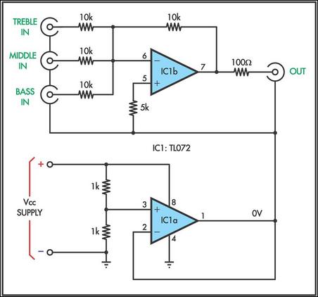
Fig.8: here is the adder circuit we used to produce the diagram shown in Fig.5. You don't have to make one of these unless you are interested in measuring your own circuit.
Here they discuss lobing errors, driver alignment & phase correction, phase shift vs frequency etc.
Having decided on your crossover frequencies, you can start assembly of the PC board by closely checking it for shorts between tracks, open circuits etc, against the pattern opposite.
Then install all the resistors, followed by the capacitors and multi-turn trimpots. Make sure that the electrolytic capacitors are installed the right way around. The bipolar electro-lytics are not polarised and can go in either way.
Ideally, 1% capacitors should be used in all of the filter circuitry. As an alternative, purchase a bag of 100 capacitors of the value you require and pick the 20 that are the closest in value to each other, using a capacitance meter or DMM with capacitance ranges.
Next, install the two regulators which are laid flat on the PC board. Be careful not to swap them over otherwise the circuit definitely won't work and you may have to replace quite a few damaged semiconductors. Finally, you can install the op amps and the RCA sockets.
You will then need to wire up the power transformer, using the diagram of Fig.7. Temporarily install the PC board into the chassis and you are ready for some voltage checks.
Voltage check
Apply power and check the regulated supply rails with your digital multimeter. They should be close to ±15V DC.
Then check that +15V is present at pin 4 of each TL074 and that -15V is present at pin 11 of each IC. Lightly touch each IC to ensure that none of them are getting hot - they should all be cool.

This photo of an early prototype PC board shows the general layout of components. It should be noted that there have been substantial changes since this photo was taken, particularly along the bottom (rear) of the board. The component overlay (Fig.6) shows the final version.
The next step is to align the whole circuit using the trimpots. This is a simple matter of setting up each output for unity gain in its passband. This can be done at three frequencies, say 100Hz for the bass, 1kHz for the midrange and 12kHz for the treble.
You will need an audio oscillator and a digital multimeter with an AC frequency response to 20kHz or better. Connect your audio oscillator to the input RCA connector in one channel. Set the frequency to 100Hz, 1kHz or 12kHz, depending on which section you wish to align. Set the level of the oscillator to 1V RMS.
Then measure the signal level at the output of the stage that you are adjusting. For the treble output, use 10kHz and adjust trimpot VR1 (left channel) or VR4 (right channel) to obtain 1V RMS at the output socket.
Similarly, for the midrange, use 1kHz and adjust VR2 (left channel) or VR5 (right channel) to obtain 1V RMS at the output sockets.
Finally, for the bass, use 100Hz and adjust VR3 (left channel) or VR6 (right channel) to obtain 1V RMS at the output. That done, it is now a matter of finally completing the wiring inside the case and checking it before connecting the unit to your amplifiers.
Your amplifiers
We mentioned before that six amplifiers are required; one for each of the bass, midrange and treble speakers, times two (for stereo). But what amplifiers should you use?
Typically, the woofer amplifier needs to be about double the power of the midrange and tweeter amplifiers, to take into account the lower sensitivity of the woofers.

The completed project showing the rear panel arrangement, power supply wiring and PC board placement. Use this in conjunction with Fig.7 (above) during final assembly.
So if you have been running a 100W per channel stereo amplifier into your 3-way speaker system, you will still need two 100W amplifiers for the woofers (eg, your exisiting amplifier!) but you can get away with two 50W amplifiers for each of the midrange and tweeters (ie, four total).
You may be able to put back into service an amplifier that you pensioned off as "underpowered".
Or, if you want to go the whole hog and build new amplifiers to go with your new active crossover, you could do a lot worse than the new SC480 amplifier module featured in this issue for the mid-range and treble.
The Ultra LD (Nov, Dec 2001, Jan 2002) or even the Plastic Power module (April 1996) would make a superb bass amplifier.
Connection
There are no screws holding the PC board in place. Instead it sits on self-adhesive holders (as used in many computers) and the RCA sockets on the back panel are themselves held in by screws.
It is simply a matter of connecting the stereo outputs from the 3-Way Active Cross-over to the appropriate bass, mid-range and treble stereo amplifier inputs, then connecting the amplifiers' outputs direct to the appropriate drivers in each of the speaker enclosures.
Needless to say, the existing crossover network in the speaker enclosures is disconnected completely - and you will need to put an extra two sets of terminals on the back of your enclosures with each of the three connected directly to a driver (and appropriately labelled).
The tone controls should ideally be flat on all amplifiers (although that can be a matter of individual taste - but the treble control won't do much on the bass amplifier nor the bass control on the treble amplifier!).
Volume controls can be individually adjusted to get the best balance between the bass, midrange and treble speakers.
Specifications
|
| Parts List 3-Way Active Crossover 1 1RU rack-mounting case, Altronics H-5011 or equivalent 1 PC board, code 01101031, 219 x 99mm 1 IEC power socket 1 chassis-mount safety fuseholder (3AG or M205 type) 1 0.5A fuse (3AG or M205 type to suit fuseholder) 1 DPST rocker switch with inbuilt neon (S1) 1 20VA toroidal transformer with 2 15V secondaries 1 3-way insulated terminal block 4 dual gold-plated RCA PC-mounting sockets, Altronics P-0212 or equivalent 6 multi-turn 100kΩ trimpots (VR1-VR6), Altronics R-2382A or equivalent Semiconductors 6 TL074 quad FET-input op amps (IC-IC6) 1 7815 positive 3-terminal regulator 1 7915 negative 3-terminal regulator 4 1N4004 silicon diodes (D1-D4) Capacitors 2 1000μF 25V PC electrolytic 2 100μF 25V PC electrolytic 2 1μF 50V bipolar electrolytic 14 100nF (0.1μ) multi-layer ceramic (code 100n or 104) 20 47nF (.047μ) metallised polyester (code 47n or 473) 20 2.2nF (.0022μF) metallised polyester (code 2n2 or 222) 2 220pF ceramic Resistors (1% metal film) 2 47kΩW (yellow violet orange brown or yellow violet black red brown) 8 20kΩ (red black orange brown or red black black red brown) 38 10kΩ (brown black orange brown or brown black black red brown) 4 100Ω (brown black brown brown or brown black black black brown) |
| R | C | 2R | Crossover Frequency |
| (kΩ) | (nF) | (kΩ) | (Hz) |
| 15 | 47 | 30 | 160 |
| 15 | 39 | 30 | 192 |
| 12 | 47 | 24 | 200 |
| 11 | 47 | 22 | 218 |
| 15 | 33 | 30 | 227 |
| 10 | 47 | 20 | 239 |
| 12 | 39 | 24 | 240 |
| 11 | 39 | 22 | 262 |
| 15 | 27 | 30 | 278 |
| 12 | 33 | 24 | 284 |
| 10 | 39 | 20 | 289 |
| 11 | 33 | 22 | 310 |
| 7.5 | 47 | 15 | 319 |
| 15 | 22 | 30 | 341 |
| 10 | 33 | 20 | 341 |
| 12 | 27 | 24 | 347 |
| 11 | 27 | 22 | 379 |
| 7.5 | 39 | 15 | 385 |
| 10 | 27 | 20 | 417 |
| 12 | 22 | 24 | 426 |
| 7.5 | 33 | 15 | 455 |
| 11 | 22 | 22 | 465 |
| 10 | 22 | 20 | 512 |
| 7.5 | 27 | 15 | 556 |
| 7.5 | 22 | 15 | 682 |
| 15 | 4.7 | 30 | 1596 |
| 15 | 3.9 | 30 | 1924 |
| 12 | 4.7 | 24 | 1995 |
| 11 | 4.7 | 22 | 2177 |
| 15 | 3.3 | 30 | 2274 |
| 10 | 4.7 | 20 | 2394 |
| 12 | 3.9 | 24 | 2405 |
| 11 | 3.9 | 22 | 2623 |
| 15 | 2.7 | 30 | 2779 |
| 12 | 3.3 | 24 | 2842 |
| 10 | 3.9 | 20 | 2886 |
| 11 | 3.3 | 22 | 3100 |
| 7.5 | 4.7 | 15 | 3193 |
| 15 | 2.2 | 30 | 3410 |
| 10 | 3.3 | 20 | 3410 |
| 12 | 2.7 | 24 | 3473 |
| 11 | 2.7 | 22 | 3789 |
| 7.5 | 3.9 | 15 | 3848 |
| 10 | 2.7 | 20 | 4168 |
| 12 | 2.2 | 24 | 4263 |
| 7.5 | 3.3 | 15 | 4547 |
| 11 | 2.2 | 22 | 4650 |
| 10 | 2.2 | 20 | 5115 |
| 7.5 | 2.7 | 15 | 5558 |
| 7.5 | 2.2 | 15 | 6821 |
Source: http://archive.siliconchip.com.au/cms/A_30278/article.html
_________________
3rd member of STTM
former 4th member
Hertz- Admin

- Posts : 1822
Join date : 2010-08-12
Age : 44
Location : Cagayan De Oro City
![]()
![]()
Re: 3 Way Active Crossover (From Siliconchip)
![]() by arkin Wed Aug 21, 2013 7:47 pm
by arkin Wed Aug 21, 2013 7:47 pm
may local version din nyan,nkita ko sa EE matagal na.

arkin- D Battery

- Posts : 446
Join date : 2011-12-02
![]()
![]()
Re: 3 Way Active Crossover (From Siliconchip)
![]() by james Sat Aug 24, 2013 9:23 pm
by james Sat Aug 24, 2013 9:23 pm
Patanda na muna nito mga sir.

james- 24V BATTERY

- Posts : 1081
Join date : 2011-11-14
![]()
![]()
Re: 3 Way Active Crossover (From Siliconchip)
![]() by ultrasonic™ Wed Sep 04, 2013 1:56 pm
by ultrasonic™ Wed Sep 04, 2013 1:56 pm
naudlot ang projz ko nito noon..
kinulang ako sa budget eh
xa nga pala mga sis.. papost ng mga pwdeng pangreplace na OP-amp
just in case na di available ang mga nabanggit sa taas
Tia
_________________
6th member of STTM
former 2nd member
im always walking on the rain so that no one could see me crying

ultrasonic™- 24V BATTERY
- Posts : 4476
Join date : 2010-08-19
Age : 38
Location : Davao City
![]()
![]()
Re: 3 Way Active Crossover (From Siliconchip)
![]() by DJFEL Wed Sep 04, 2013 10:37 pm
by DJFEL Wed Sep 04, 2013 10:37 pm
may ron ky PT neto sa elab yata...

DJFEL- 24V BATTERY
- Posts : 1780
Join date : 2012-11-21
Age : 42
Location : SIUIJOR
![]()
![]()
Re: 3 Way Active Crossover (From Siliconchip)
![]() by arkin Thu Sep 05, 2013 8:52 pm
by arkin Thu Sep 05, 2013 8:52 pm
@ ultra,pwede dyan LF444CN at LF347 sis.localy available yan.gmit ko yan pra sa subwoofer pre driver at 3 way active crossover.murang-mura lng[pra sa mga kuripot kagaya ko:lol!: ]
arkin- D Battery
- Posts : 446
Join date : 2011-12-02
![]()
![]()
Re: 3 Way Active Crossover (From Siliconchip)
![]() by Hertz Fri Sep 06, 2013 1:50 pm
by Hertz Fri Sep 06, 2013 1:50 pm
meron nga nyanarkin wrote:may local version din nyan,nkita ko sa EE matagal na.
pwede rin LM324 at TL084CN
_________________
3rd member of STTM
former 4th member
Hertz- Admin
- Posts : 1822
Join date : 2010-08-12
Age : 44
Location : Cagayan De Oro City
![]()
![]()
james- 24V BATTERY
- Posts : 1081
Join date : 2011-11-14
![]()
![]()
Re: 3 Way Active Crossover (From Siliconchip)
![]() by arkin Sat Sep 07, 2013 6:06 pm
by arkin Sat Sep 07, 2013 6:06 pm
@hertz,ntry ko na i-replace ang lm324 sa lf444cn,ok nman.pro feel ko prang nkukulangan ako sa resulta,kya lf444cn plaging gmit ko[feel ko lng ha:D]
@james,dual lng ang 4558,samantalang quad yong mga nabanggit sa itaas.
lm324 & tl084 kadalasan gmit yan sa tone control ng mga amplifier.pro,pareho lng ang pin config ng mga ic na yan.magkaiba lng sila ng gain bandwidth.
@james,dual lng ang 4558,samantalang quad yong mga nabanggit sa itaas.
lm324 & tl084 kadalasan gmit yan sa tone control ng mga amplifier.pro,pareho lng ang pin config ng mga ic na yan.magkaiba lng sila ng gain bandwidth.
arkin- D Battery
- Posts : 446
Join date : 2011-12-02
![]()
![]()
Re: 3 Way Active Crossover (From Siliconchip)
![]() by DJFEL Mon Sep 09, 2013 8:54 am
by DJFEL Mon Sep 09, 2013 8:54 am
post ang naka asemble na dito..
DJFEL- 24V BATTERY
- Posts : 1780
Join date : 2012-11-21
Age : 42
Location : SIUIJOR
![]()
![]()
Re: 3 Way Active Crossover (From Siliconchip)
![]() by DJFEL Mon Sep 09, 2013 8:55 am
by DJFEL Mon Sep 09, 2013 8:55 am
pang ma tapos ko yong ebang project ko dito...baka eto yong sonod ko..
DJFEL- 24V BATTERY
- Posts : 1780
Join date : 2012-11-21
Age : 42
Location : SIUIJOR
![]()
![]()
![]()
» 2.1-Tunable-Crossover-Network_combined by 576Pinoy_Tech
» Electronic Crossover (LMH Filter) by 576Pinoy_Tech
» Ano po ang pinagkaiba ng Active component sa Passive Component ?
» Electronic Crossover (LMH Filter) by 576Pinoy_Tech
» Ano po ang pinagkaiba ng Active component sa Passive Component ?
Page 1 of 1
Permissions in this forum:
You cannot reply to topics in this forum