
Starting with Robots
Page 1 of 1
![]()
 Starting with Robots
![]() by pyroelectro Tue Apr 19, 2011 10:59 pm
by pyroelectro Tue Apr 19, 2011 10:59 pm
We get quite a lot of of enquiries from would-be contestants for Robot Wars who don't know where to start building their robot. I sometimes get the impression that they are starting with the controller - which is the wrong end of the design chain. As a general rule, when designing a machine, you should design a mechanism that will do exactly what is required before you start working out how to control it. I used to work in the welding industry, designing control systems for automatic welding machines and my brief to the drawing office always was 'You design me a machine that does what the mechanical spec requires and I'll control it'.
A robot is a complicated system where mechanics and electronics interact with a human to give the required result. In all mechanical/electronic systems you must first consider the mechanics. However good the electronics, it will never compensate for a bad mechanical design. On the other hand a good mechanical design may require little electronics!
Types of drive/control system
There are two main families of drive systems for a machine such as a robot:
1. To use a single drive motor with a separate steering system. This is of course how most radio controlled cars are designed and is the market most radio controllers are aimed at. This is a 'Drive and Steer' machine.
2. To use two drive motors and to control the steering by differential speed control, using two reversing speed controllers. It is this system which seems to suit most robot builders - it has the benefit of giving better manoeuvrability. This is a 'Differential Drive' or 'Skid steer' machine.
Of course variations on the above are possible, such as 4 wheel drive, walking machines etc. But all the robots that I recall seeing on Robot Wars are one or other of the above categories. However I doubt that this list is exhaustive!
It is probably useful to note that the mechanisms, as listed, are in increasing order of control complexity.
1. Drive and Steer
*Powered Castor
Here a single drive wheel is power pivoted so that drive is in any direction, as shown in the drawing. The body of the machine sorts itself out, depending on friction and centre of mass, following the pivoted drive wheel.
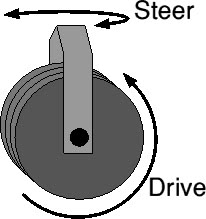
If the drive wheel is free to rotate continuously (which would need slip rings for the drive motor power) the drive requires no direction control as this is done simply by pivoting the wheel 180 degrees. For most such machines the steering 'pivot' could be motorised at constant speed, so such a machine would require a very simple control system consisting of two relays (one for forward, one for reverse) and one motor speed control without reversing. A suitable motor speed control might be our 2QD series or Scoota (which also give regen braking).
An interesting variety of such a machine would be a sphere with the mechanism inside, to make a steerable sphere! Problem with this is that it would be difficult to steer by remote as there would be no visible indication of which direction the mechanism was pointing. You could of course use a transparent sphere!
*Automobile style
This is the original steering system used for autos with rear wheel drive and separate front wheel steering. Not very manoeuvrable for a robot! Modern autos use front wheel drive, where the drive wheels are steered and this system, used in a robot, could be mechanically very similar to a differential drive machine! It would have a simpler control system as it needs a steering motor (forward and reverse, fixed speed) with a single reversing controller. A suitable controller would be one of our VTX series controllers - this is a redesign of our original NCC and one target application of these was for kiddiecars and the 'NCC' bit actually arose from 'Noddy Car Controller'!
The simplest Robot using this system would of course be a 3 wheeler, or even a 2 wheeler with 'stabilizer' on each side.
This steering system may seem simple: however it is almost entirely a mechanical solution. In an auto, the solution consists of a mechanical linkage to the steering wheel and in getting the steering geometry correct (no simple task). An electrical control system might involve, in essence, an electric motor to drive the 'steering wheel' - but this solves no mechanical problems. Instead it exacerbates them: the motor speed and gearing has to be correct, and you need some way of limiting the travel, and also of detecting when the travel is at the limit so the motor can be stopped.
Of course for robot use it might well be simpler to make a high powered servo actuator. After all the radio control servo simply moves an arm through an angle and you should be able to link this to a steering system!
All of these suggestions do not, you will note, involve speed control! Which means that 4QD cannot get usefully involved in individual solutions.
2. Differential Drive
When a machine with two spaced wheels (on a common axle or separated) goes round a corner, the outer wheel has to travel further than the inner, as shown in the diagram. This is the reason why autos have to have a differential gear.
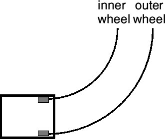
This difference in distance travelled is not only the reason a differential gear is needed but is also the mechanism that causes differential drive to work. In the differential drive, a pair of wheels (one each side) are powered and under individual control, so that the two may be operated at different speed. If one wheel is rotated faster than the other, then the machine is forced to turn as shown in the diagram above.
It should be obvious from the above that a differential control system requires two motor speed controllers - although these may be in a common box masquerading as a single controller. Moreover if the machine is to turn 'on the spot' then each controller must be able to reverse direction totally independently. There are in essence two types of system for controlling such a vehicle.
*Tank mode - or Independent control.
Otherwise called 'tank style' where two separate channels are used, each with a single 'stick'. Moving one stick speeds or slows one motor only. Such a system might use two VTX controllers with two separate Joystick interfaces (JSB-001 or JSA-002). The basic controller has a speed input (which might be used with a throttle pedal) and a reversing input (from a forward/reverse switch). A combined speed and direction lever (aka Joystick or wig-wag control) is a potentiometer which causes zero speed in the centre. Move the lever forward to move forward and back to move backwards. The 'Joystick interface' contains the simple circuit to translate this centre-zero control into the required speed and direction input.
It should be noticed that a true tracked vehicle can take a lot of power (motor current) to turn 'on the spot' as the diagram should make clear.
The green arrows show the machine turning about its centre. At the ends of the tracks the arrows are nearly at right angles to the track: movement along the track's running direction is minimal and the ends of the track are having to slide sideways, so if the track has a god grip, turning will be nearly impossible! Only near the centre of the track is the track not sliding sideways.
Clearly the longer the track is, the worse the effect and the wider the tracks are apart, the better the turning ability. If the tracks are wide enough apart (in relation to their length) then the nearer they behave to two normal wheels.
To reduce the turning friction, drive on two wheels and allow the non driven wheel(s) to pivot, castor style, so they don't slide sideways. Don't forget that there is a similar drag effect with wide wheels!
*Speed and Steer control.
Also called Differential Control.
Two drive wheels are controlled each by their own motor and motor speed controller. A joystick is used as the control: moving this front to back alters the speed (and direction) of both motors together so the machine moves in a straight line. Moving the stick from side to side reduces the speed of one motor whilst increasing the speed of the other, causing the vehicle to turn.
Most radio control systems have two separate sticks, one for speed (front and back) and a second for Steer (side to side) but the principle is the same as for a dual axis stick.
Of course, if the machine's speed is slow, the controller will need to reverse one wheel to cause a turn. The Dual Channel Interface looks after all of this, and had adjustable speed and Steer performance, including a 'Mix' control which affects the steering response. This is a very popular method of motor speed control which has been used a lot. The most popular system is a 'Dual Channel Interface' with two VTX-75 controllers. Smaller Robots use VTX-40s and some are going for Pro-120s or even the 4QD series controllers!
Control Systems
Now let us look in more detail at the available controllers and the ways you can implement (and enhance) various systems. You will find a list of hot links at the end of this page. It may seem at first glance that 4QD offer too many parts and selection can seem quite complicated. However this 'building block' system does have one large advantage: you can assemble almost any control system from a simple, economical, single quadrant control system to a full two channel 4 quadrant system capable of handling 300 amps per channel! So you can design your own system! If you browse the electronics section of our site, you will even find circuits and advice on building your own controller!
Motor speed controllers
If you are not used to motor speed controller 'jargon' then we suggest you take our Guided Tour of controller features.
We offer no fewer that five families of single and two quadrant controllers.
4QD manufacture several non reversing controllers. The porter is a simple controller, with regen braking. The Uni series are slightly more sophisticated, with slightly different features.
Next come the VTX series: reversing controllers. You can reverse a permanent magnet motor simply by swapping over the wires with a double-pole changeover switch. However if you do that at speed, all the mechanical energy is 'dumped' into the switch or the controller. It would be a bit like throwing your car into reverse at 90 mph. Problem is that, whereas nobody would dream of doing that to a car, electrical machines are different and people do expect to do exactly that with an electric motor. So reversing controllers have to reverse safely. We use a 'dual ramp' reversing system in all controllers.
Pro-120 is similar to VTX, with more features and our top end four quadrant are the 4QD series. The 4QD series also have 'wig-way' (aka Joystick) input option.
Dual Channel Interface
Our controllers are, in general, 'single-ended' in that the speed input is a zero to full speed input (like a car's throttle) with a separate forward/reverse input (like the car's gear lever). The exception to this is the 4QD series which can be set, on-board, for centre-zero operation or single-ended.
So an interface is usually required to give a centre zero operation. We do a range of interfaces ranging from single ones to the new Dual Channel Interfaces which can give either sum and difference steering. See Joystick Interface Boards
Most popular choices
So which controllers ar we selling? By far the most popular choice is a Dual Channel Interfaces (DCI-111) with two VTX-75-24. Most commonly used with two Bosch 750w motors.
Some people are using two Pro-120 with the Bosch, but see the FAQ sheet on this.
We've also sold 4QD series controllers, even 4QD-300s for robots and we know of more than one than using two Lynch motors in their robot! I wonder how far sheet brute force will take them!
Radio Control Interface
4QDs motor speed controllers are designed for vehicle applications such as golf buggies rather than as radio control ESCs so they do not accept directly the signal from a standard radio control receiver but require some sort of interface. 4QD ofer two options.
Option 1
The easiest radio control uses the standard radio control servo. The servo is mechanicaly coupled to a pot which operates the speed controller in the normal way.
This has the advantage of simplicity and visibility. Furthermore the mechanical linkage acts as a good barrier to interference that is produced by the motor brushgear and which may interfere with the radio receiver.
4QDs Joystick interfaces all work this way. The most common one is the DCI-111 which is a Dual Channel interface with on-board mixing so that is can simply be used with either separate channels or as a 'speed and steer' system with adjustable mixing.
Wiring of the DCI-111 'Dual Channel Interface' with two controllers is very simple.
If you want more technical information, see the following two pages.
* Pulse Width Position Servo
* Radio Control Interface
Several roboteers have brewed their own interface using microcontrollers with varying degrees of success.
Option 2
4QD now produce a Radio Control interface which accepts directly the signal from the standard radio received and changes it to suit the controller. See Radio Control Interfaces.
Option 3
Several third partes have produced electronic interfaces, based around PIC microcontrollers, which can translate the radio control pulses into speed and direction signals for the controllers.
Microcontrollers
A sophisticated robot can get quite complex and it is possible to ue a microcontroller to process the pulses from the receiver and to measure parameters in the robot and to control the motors (and weapons) in a far more sophisticated fashion. In such a machine you would simply use 4QD's controllers as a 'power amplifier' to interface between the micro and the motors. There is a section in our FAQ pages on Microprocessor control but this is a large area where we shall probably be expanding our www site.
Suppression
One thing that bothers roboteers is interference. 4QD controllers are used in a high proportion of the larger robots and we have never been able to identify a case of interference caused by the controllers. However it is advisable to suppress the motors. The only recommendation is that you connect some small ceramic capacitors (10n) across the brushes. Ideally you need to disassemble the motors and fit one capacitor across the brushes, inside the motor. If there are more than two brushes, fit one capacitor across each pair of brushes. Failing that, connect a single 10n ceramic across the motor terminals, as close to the motor body as possible. Do not connect any capacitor from motor terminals to the chassis: this is only good practise if you can be sure of the radio frequency characteristics of the chassis. In most robots that is an unknown! Such capacitors may cause problems rather than cure them.
A properly designed RFI suppression system will have a box that is a complete Faraday cage, with no holes, and with all metalwork bonded carefully together. All electronics will be within the cage and special attention is paid to any wires that penetrate the cage. It is for this type of shielding system that the admonition to connect capacitors from brushes to chassis exists, but in practise, I believe that no robot I have seen on Robot Wars is thus designed and if the cage is imperfect, interference coupled to it via these chassis connected capacitors is more likely to increase radiated interference than to reduce it.
If the motor wires are long enough to warrant it, twist them together. Same with the battery wires. Also remember that motor and battery wires are high current, pulsing. Keep them well away from other wiring, and well away from the receiver.
The network which was recommended by the RW hints and tips includes a 470n capacitor across the brushes. At 20kHz (the switching frequency used) a 470n has an impedance of only 17 ohms, so as the switching waveform is a squarewave, several amps of pwm switching will flow through it causing it maybe to get hot! It is far too large a value. In any case, such a high value will be polyester, wound from foil. This construction is not good at high frequencies because it can have a high self-inductance.
Furthermore, one end of the motor is connected to battery positive (which end depends on which direction the robot's going) and the other is switching between battery positive and battery negative (because of the pwm switching). Two 47n capacitors form a reasonably low impedance (170 ohms each to 20kHz) potential divider, so the junction will try to be a pwm waveform at 20hHz of half the battery voltage. Surely you do not want that sort of voltage/current on your robot's chassis!
Fourier analysis of a squarewave says that the waveform consists of the fundamental frequency (in our case 24v p-p of 20kHz) plus 1/3 of its amplitude of 3rd harmonic (8v p-p at 60kHz), plus 1/5 5th harmonic (5v p-p at 100kHz) and so on. Since the capacitors impedance reduces in proportion to the frequency, you can see that the harmonic currents flowing in these capacitor can get quite large at higher frequencies. Suppression is meant to remove unwanted signals - not to put wanted signals in the wrong place.
RFI suppression is an art more than a science: there are good things to do and bad things, but in the end it's always down to empirical testing! Get a portable radio and see how close to the robot you can get it before interference totally drowns out the reception. Try various things to see what improves the situation and what makes it worse.
source: radiolocman
A robot is a complicated system where mechanics and electronics interact with a human to give the required result. In all mechanical/electronic systems you must first consider the mechanics. However good the electronics, it will never compensate for a bad mechanical design. On the other hand a good mechanical design may require little electronics!
Types of drive/control system
There are two main families of drive systems for a machine such as a robot:
1. To use a single drive motor with a separate steering system. This is of course how most radio controlled cars are designed and is the market most radio controllers are aimed at. This is a 'Drive and Steer' machine.
2. To use two drive motors and to control the steering by differential speed control, using two reversing speed controllers. It is this system which seems to suit most robot builders - it has the benefit of giving better manoeuvrability. This is a 'Differential Drive' or 'Skid steer' machine.
Of course variations on the above are possible, such as 4 wheel drive, walking machines etc. But all the robots that I recall seeing on Robot Wars are one or other of the above categories. However I doubt that this list is exhaustive!
It is probably useful to note that the mechanisms, as listed, are in increasing order of control complexity.
1. Drive and Steer
*Powered Castor
Here a single drive wheel is power pivoted so that drive is in any direction, as shown in the drawing. The body of the machine sorts itself out, depending on friction and centre of mass, following the pivoted drive wheel.
If the drive wheel is free to rotate continuously (which would need slip rings for the drive motor power) the drive requires no direction control as this is done simply by pivoting the wheel 180 degrees. For most such machines the steering 'pivot' could be motorised at constant speed, so such a machine would require a very simple control system consisting of two relays (one for forward, one for reverse) and one motor speed control without reversing. A suitable motor speed control might be our 2QD series or Scoota (which also give regen braking).
An interesting variety of such a machine would be a sphere with the mechanism inside, to make a steerable sphere! Problem with this is that it would be difficult to steer by remote as there would be no visible indication of which direction the mechanism was pointing. You could of course use a transparent sphere!
*Automobile style
This is the original steering system used for autos with rear wheel drive and separate front wheel steering. Not very manoeuvrable for a robot! Modern autos use front wheel drive, where the drive wheels are steered and this system, used in a robot, could be mechanically very similar to a differential drive machine! It would have a simpler control system as it needs a steering motor (forward and reverse, fixed speed) with a single reversing controller. A suitable controller would be one of our VTX series controllers - this is a redesign of our original NCC and one target application of these was for kiddiecars and the 'NCC' bit actually arose from 'Noddy Car Controller'!
The simplest Robot using this system would of course be a 3 wheeler, or even a 2 wheeler with 'stabilizer' on each side.
This steering system may seem simple: however it is almost entirely a mechanical solution. In an auto, the solution consists of a mechanical linkage to the steering wheel and in getting the steering geometry correct (no simple task). An electrical control system might involve, in essence, an electric motor to drive the 'steering wheel' - but this solves no mechanical problems. Instead it exacerbates them: the motor speed and gearing has to be correct, and you need some way of limiting the travel, and also of detecting when the travel is at the limit so the motor can be stopped.
Of course for robot use it might well be simpler to make a high powered servo actuator. After all the radio control servo simply moves an arm through an angle and you should be able to link this to a steering system!
All of these suggestions do not, you will note, involve speed control! Which means that 4QD cannot get usefully involved in individual solutions.
2. Differential Drive
When a machine with two spaced wheels (on a common axle or separated) goes round a corner, the outer wheel has to travel further than the inner, as shown in the diagram. This is the reason why autos have to have a differential gear.
This difference in distance travelled is not only the reason a differential gear is needed but is also the mechanism that causes differential drive to work. In the differential drive, a pair of wheels (one each side) are powered and under individual control, so that the two may be operated at different speed. If one wheel is rotated faster than the other, then the machine is forced to turn as shown in the diagram above.
It should be obvious from the above that a differential control system requires two motor speed controllers - although these may be in a common box masquerading as a single controller. Moreover if the machine is to turn 'on the spot' then each controller must be able to reverse direction totally independently. There are in essence two types of system for controlling such a vehicle.
*Tank mode - or Independent control.
Otherwise called 'tank style' where two separate channels are used, each with a single 'stick'. Moving one stick speeds or slows one motor only. Such a system might use two VTX controllers with two separate Joystick interfaces (JSB-001 or JSA-002). The basic controller has a speed input (which might be used with a throttle pedal) and a reversing input (from a forward/reverse switch). A combined speed and direction lever (aka Joystick or wig-wag control) is a potentiometer which causes zero speed in the centre. Move the lever forward to move forward and back to move backwards. The 'Joystick interface' contains the simple circuit to translate this centre-zero control into the required speed and direction input.
It should be noticed that a true tracked vehicle can take a lot of power (motor current) to turn 'on the spot' as the diagram should make clear.
The green arrows show the machine turning about its centre. At the ends of the tracks the arrows are nearly at right angles to the track: movement along the track's running direction is minimal and the ends of the track are having to slide sideways, so if the track has a god grip, turning will be nearly impossible! Only near the centre of the track is the track not sliding sideways.
Clearly the longer the track is, the worse the effect and the wider the tracks are apart, the better the turning ability. If the tracks are wide enough apart (in relation to their length) then the nearer they behave to two normal wheels.
To reduce the turning friction, drive on two wheels and allow the non driven wheel(s) to pivot, castor style, so they don't slide sideways. Don't forget that there is a similar drag effect with wide wheels!
*Speed and Steer control.
Also called Differential Control.
Two drive wheels are controlled each by their own motor and motor speed controller. A joystick is used as the control: moving this front to back alters the speed (and direction) of both motors together so the machine moves in a straight line. Moving the stick from side to side reduces the speed of one motor whilst increasing the speed of the other, causing the vehicle to turn.
Most radio control systems have two separate sticks, one for speed (front and back) and a second for Steer (side to side) but the principle is the same as for a dual axis stick.
Of course, if the machine's speed is slow, the controller will need to reverse one wheel to cause a turn. The Dual Channel Interface looks after all of this, and had adjustable speed and Steer performance, including a 'Mix' control which affects the steering response. This is a very popular method of motor speed control which has been used a lot. The most popular system is a 'Dual Channel Interface' with two VTX-75 controllers. Smaller Robots use VTX-40s and some are going for Pro-120s or even the 4QD series controllers!
Control Systems
Now let us look in more detail at the available controllers and the ways you can implement (and enhance) various systems. You will find a list of hot links at the end of this page. It may seem at first glance that 4QD offer too many parts and selection can seem quite complicated. However this 'building block' system does have one large advantage: you can assemble almost any control system from a simple, economical, single quadrant control system to a full two channel 4 quadrant system capable of handling 300 amps per channel! So you can design your own system! If you browse the electronics section of our site, you will even find circuits and advice on building your own controller!
Motor speed controllers
If you are not used to motor speed controller 'jargon' then we suggest you take our Guided Tour of controller features.
We offer no fewer that five families of single and two quadrant controllers.
4QD manufacture several non reversing controllers. The porter is a simple controller, with regen braking. The Uni series are slightly more sophisticated, with slightly different features.
Next come the VTX series: reversing controllers. You can reverse a permanent magnet motor simply by swapping over the wires with a double-pole changeover switch. However if you do that at speed, all the mechanical energy is 'dumped' into the switch or the controller. It would be a bit like throwing your car into reverse at 90 mph. Problem is that, whereas nobody would dream of doing that to a car, electrical machines are different and people do expect to do exactly that with an electric motor. So reversing controllers have to reverse safely. We use a 'dual ramp' reversing system in all controllers.
Pro-120 is similar to VTX, with more features and our top end four quadrant are the 4QD series. The 4QD series also have 'wig-way' (aka Joystick) input option.
Dual Channel Interface
Our controllers are, in general, 'single-ended' in that the speed input is a zero to full speed input (like a car's throttle) with a separate forward/reverse input (like the car's gear lever). The exception to this is the 4QD series which can be set, on-board, for centre-zero operation or single-ended.
So an interface is usually required to give a centre zero operation. We do a range of interfaces ranging from single ones to the new Dual Channel Interfaces which can give either sum and difference steering. See Joystick Interface Boards
Most popular choices
So which controllers ar we selling? By far the most popular choice is a Dual Channel Interfaces (DCI-111) with two VTX-75-24. Most commonly used with two Bosch 750w motors.
Some people are using two Pro-120 with the Bosch, but see the FAQ sheet on this.
We've also sold 4QD series controllers, even 4QD-300s for robots and we know of more than one than using two Lynch motors in their robot! I wonder how far sheet brute force will take them!
Radio Control Interface
4QDs motor speed controllers are designed for vehicle applications such as golf buggies rather than as radio control ESCs so they do not accept directly the signal from a standard radio control receiver but require some sort of interface. 4QD ofer two options.
Option 1
The easiest radio control uses the standard radio control servo. The servo is mechanicaly coupled to a pot which operates the speed controller in the normal way.
This has the advantage of simplicity and visibility. Furthermore the mechanical linkage acts as a good barrier to interference that is produced by the motor brushgear and which may interfere with the radio receiver.
4QDs Joystick interfaces all work this way. The most common one is the DCI-111 which is a Dual Channel interface with on-board mixing so that is can simply be used with either separate channels or as a 'speed and steer' system with adjustable mixing.
Wiring of the DCI-111 'Dual Channel Interface' with two controllers is very simple.
If you want more technical information, see the following two pages.
* Pulse Width Position Servo
* Radio Control Interface
Several roboteers have brewed their own interface using microcontrollers with varying degrees of success.
Option 2
4QD now produce a Radio Control interface which accepts directly the signal from the standard radio received and changes it to suit the controller. See Radio Control Interfaces.
Option 3
Several third partes have produced electronic interfaces, based around PIC microcontrollers, which can translate the radio control pulses into speed and direction signals for the controllers.
Microcontrollers
A sophisticated robot can get quite complex and it is possible to ue a microcontroller to process the pulses from the receiver and to measure parameters in the robot and to control the motors (and weapons) in a far more sophisticated fashion. In such a machine you would simply use 4QD's controllers as a 'power amplifier' to interface between the micro and the motors. There is a section in our FAQ pages on Microprocessor control but this is a large area where we shall probably be expanding our www site.
Suppression
One thing that bothers roboteers is interference. 4QD controllers are used in a high proportion of the larger robots and we have never been able to identify a case of interference caused by the controllers. However it is advisable to suppress the motors. The only recommendation is that you connect some small ceramic capacitors (10n) across the brushes. Ideally you need to disassemble the motors and fit one capacitor across the brushes, inside the motor. If there are more than two brushes, fit one capacitor across each pair of brushes. Failing that, connect a single 10n ceramic across the motor terminals, as close to the motor body as possible. Do not connect any capacitor from motor terminals to the chassis: this is only good practise if you can be sure of the radio frequency characteristics of the chassis. In most robots that is an unknown! Such capacitors may cause problems rather than cure them.
A properly designed RFI suppression system will have a box that is a complete Faraday cage, with no holes, and with all metalwork bonded carefully together. All electronics will be within the cage and special attention is paid to any wires that penetrate the cage. It is for this type of shielding system that the admonition to connect capacitors from brushes to chassis exists, but in practise, I believe that no robot I have seen on Robot Wars is thus designed and if the cage is imperfect, interference coupled to it via these chassis connected capacitors is more likely to increase radiated interference than to reduce it.
If the motor wires are long enough to warrant it, twist them together. Same with the battery wires. Also remember that motor and battery wires are high current, pulsing. Keep them well away from other wiring, and well away from the receiver.
The network which was recommended by the RW hints and tips includes a 470n capacitor across the brushes. At 20kHz (the switching frequency used) a 470n has an impedance of only 17 ohms, so as the switching waveform is a squarewave, several amps of pwm switching will flow through it causing it maybe to get hot! It is far too large a value. In any case, such a high value will be polyester, wound from foil. This construction is not good at high frequencies because it can have a high self-inductance.
Furthermore, one end of the motor is connected to battery positive (which end depends on which direction the robot's going) and the other is switching between battery positive and battery negative (because of the pwm switching). Two 47n capacitors form a reasonably low impedance (170 ohms each to 20kHz) potential divider, so the junction will try to be a pwm waveform at 20hHz of half the battery voltage. Surely you do not want that sort of voltage/current on your robot's chassis!
Fourier analysis of a squarewave says that the waveform consists of the fundamental frequency (in our case 24v p-p of 20kHz) plus 1/3 of its amplitude of 3rd harmonic (8v p-p at 60kHz), plus 1/5 5th harmonic (5v p-p at 100kHz) and so on. Since the capacitors impedance reduces in proportion to the frequency, you can see that the harmonic currents flowing in these capacitor can get quite large at higher frequencies. Suppression is meant to remove unwanted signals - not to put wanted signals in the wrong place.
RFI suppression is an art more than a science: there are good things to do and bad things, but in the end it's always down to empirical testing! Get a portable radio and see how close to the robot you can get it before interference totally drowns out the reception. Try various things to see what improves the situation and what makes it worse.
source: radiolocman

pyroelectro- C Battery

- Posts : 288
Join date : 2010-11-23
Age : 40
Location : Cebu City
![]()
![]()
![]()
Page 1 of 1
Permissions in this forum:
You cannot reply to topics in this forum|
|
|