
10A H-Bridge Motor Controller
Page 1 of 1
![]()
 10A H-Bridge Motor Controller
![]() by pyroelectro Mon May 23, 2011 8:54 pm
by pyroelectro Mon May 23, 2011 8:54 pm
Motor control is the core heart of robotics. Without locomotion or any movement a robot is dull and lifeless. The H-bridge is a tried and true concept for DC motor control. It allows you to move motors forward, backward and with varying speeds through PWM (pulse with modulation).
This tutorial will take a few steps back from the all-in-one L298 or LMD18245 motor control ICs and look more into how we can build our own H-bridge without the need of an IC.
At first this might sound like a difficult task. How can we, tiny simple people, build something that professional manufacturers put into high power ICs? Well keep reading this tutorial and you'll find out, it's actually easy!
10A H-Bridge With PWM Input
Purpose & Overview of this project
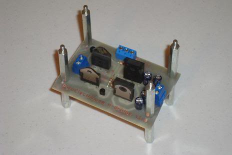
The main goal for this tutorial is to build a 10 AMP motor controller that can control a DC motor with a digital input. This way if we want to use a microcontroller to turn the motor off or on, we can. There should be one digital input for forward and one digital input for backward. Additionally the board should have two terminal blocks, one for the motor's power and one for connecting the H-bridge to the motor.
For this design darlington pair BJT power transistors will be used to form the H-bridge. This design choice has pros and cons just like anything, but for our purposes they do the trick. An alternative power transistor that could go higher than 10A would be with HEXFETs. In reality any transistors can be used to form an H-bridge, but their different properties make some better and others terrible.
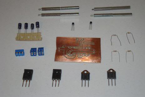
Parts
2x TIP147 PNP Transistor
2x TIP142 NPN Transistor
2x 2n2222 NPN Transistor
2x 1kΩ Resistors
2x 10kΩ Resistors
2x Dual Terminal Block
Triple Terminal Block
Dual Layer PC Board
Ferric Chloride Etchant
Clothing Iron
Platic Container
Push Buttons
DC Motor
Soldering Iron
Solder
Power Drill
Laser Printer
Glossy Paper
Parts List Details
All the parts listed above are used in this tutorial and serve a specific purpose. The main parts are described in more detail below to give you an idea of why we need them and what it is that they do.
TIP147 and TIP142
These transistor pairs are high power (125 Watt) and high current (10A) darlington pair transistors. One is an NPN type transistor, the other is PNP. They are made to fit together specifically for H-Bridge configurations. When you see the scheamtic, it will be somewhat obvious how these pairs just fit together.
2n2222 NPN Transistor
These simple 2n2222 transistors are used as buffers beteween the digital on/off side and the analog motor control side of the circuits. A simple digital signal into the 2n2222 tells the h-bridge to go forward or backwards, the theory section will go more into the details of how the h-bridge works.
1kΩ Resistors, 10kΩ
The 10kΩ resistors are used as current limiting 'buffers' between the digital and analog portions of this circuit. They will help protect against potential damage to any digital circuits controller the h-bridge. The 1kΩ resistors are also current limiting resistors so that the 2n2222 does not get damaged when it is switched on.
Dual Terminal Block and Triple Terminal Block
Two dual terminal blocks are used to connect the motor and the power supply to the H-bridge circuit. The triple terminal block is used to connect the digital control signals: Forward/Reverse/Ground to the h-bridge.
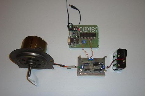
DC Motor
DC motors are one of the simplest types of motors and we'll be controlling one of those in this tutorial.
The 10A H-Bridge Motor Controller circuit looks simple but there are some key points that you don't want to miss. The main devices used in the circuit are the TIP147, TIP142 and 2n2222.
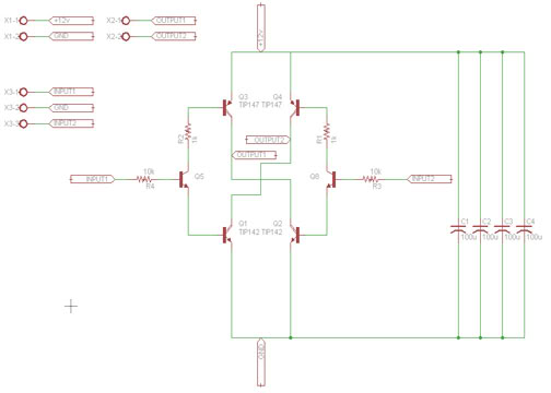
H-Bridge Schematic Specifics
•Power Circuit
The power circuit is the +12v coming in from the terminal block X1-1/X1-2. It connects to a few 100uF capacitors and you might need more or less to help the motor run smoothly. The power also connects to the very top of the H-bridge (power to collector) and the very bottom (emitter to ground).
•Motor Control Outputs
Outputs 1 and 2 are found in the middle of the H-bridge circuit, these connections feed into one of the dual terminal blocks, which connects to the DC motor. It is at these points of Output 1/2 where power will flow to drive the motor.
•Digital Control Inputs
The triple terminal block X3-1/X3-2/X3-3 offer a way to connect up some digital circuitry and a ground to control the h-bridge. Input 1 controls one side of the H-bridge and Input 2 controls the other side.

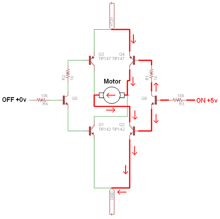
The two pictures seen above shows you the 2 possible modes of operation. Since there are only two digital inputs, you only ever need to turn one side on at a time. The two inputs should never be turned on at the same time, this will ruin your power transistors.
But as you can see. When we apply an 'on' +5v signal to one side of the H-bridge, it actives two transistors, allowing current to flow through the motor. This turns the motor one way. Similarly, when we activate the opposite side with an 'on' +5v signal, the other two transistors are turned on and the DC motor spins in the opposite direction.
Power Loss: BJT vs. MOSFET
When it comes to motor control and H-bridges, there's two types of power transistors that take the main stage. The Power BJT and Power MOSFET. The main difference between the two, at least as far as we are concerned is the power loss.

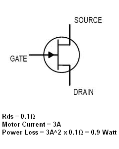
BJT transistors have an inherint Vce 0.7v drop, which with two transistors translates to a 1.4v drop. As you can see in the table above this amounts to about 4 Watt power loss if we're running at 3amps. That's a lot of power! The power MOSFET acts in a different way yielding a Rds 0.1Ω (some less some more) resistances across the transistor which means across two MOSFETs there is about a 2 Watt power loss.
At first glance these numbers seem not all that different, but as voltage and currents increases (+24v...+60v...) the MOSFET will win hands down with less powerloss. However, for our low voltage +12v H-bridge, these cheap TIP142/147's work nicely. There are other advantages for using BJT vs. MOSFET but I just wanted to show you this simple one. After you're an H-bridge building pro you can worry about becoming a professional designer.
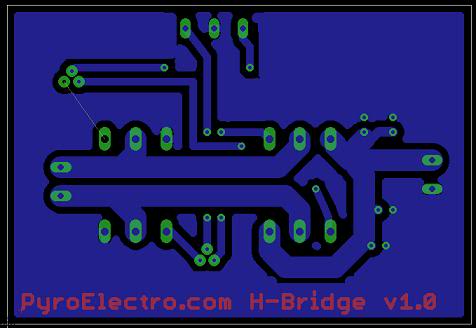
PCB LAYOUT
source: pyroelectro.com
This tutorial will take a few steps back from the all-in-one L298 or LMD18245 motor control ICs and look more into how we can build our own H-bridge without the need of an IC.
At first this might sound like a difficult task. How can we, tiny simple people, build something that professional manufacturers put into high power ICs? Well keep reading this tutorial and you'll find out, it's actually easy!
10A H-Bridge With PWM Input
Purpose & Overview of this project
The main goal for this tutorial is to build a 10 AMP motor controller that can control a DC motor with a digital input. This way if we want to use a microcontroller to turn the motor off or on, we can. There should be one digital input for forward and one digital input for backward. Additionally the board should have two terminal blocks, one for the motor's power and one for connecting the H-bridge to the motor.
For this design darlington pair BJT power transistors will be used to form the H-bridge. This design choice has pros and cons just like anything, but for our purposes they do the trick. An alternative power transistor that could go higher than 10A would be with HEXFETs. In reality any transistors can be used to form an H-bridge, but their different properties make some better and others terrible.
Parts
2x TIP147 PNP Transistor
2x TIP142 NPN Transistor
2x 2n2222 NPN Transistor
2x 1kΩ Resistors
2x 10kΩ Resistors
2x Dual Terminal Block
Triple Terminal Block
Dual Layer PC Board
Ferric Chloride Etchant
Clothing Iron
Platic Container
Push Buttons
DC Motor
Soldering Iron
Solder
Power Drill
Laser Printer
Glossy Paper
Parts List Details
All the parts listed above are used in this tutorial and serve a specific purpose. The main parts are described in more detail below to give you an idea of why we need them and what it is that they do.
TIP147 and TIP142
These transistor pairs are high power (125 Watt) and high current (10A) darlington pair transistors. One is an NPN type transistor, the other is PNP. They are made to fit together specifically for H-Bridge configurations. When you see the scheamtic, it will be somewhat obvious how these pairs just fit together.
2n2222 NPN Transistor
These simple 2n2222 transistors are used as buffers beteween the digital on/off side and the analog motor control side of the circuits. A simple digital signal into the 2n2222 tells the h-bridge to go forward or backwards, the theory section will go more into the details of how the h-bridge works.
1kΩ Resistors, 10kΩ
The 10kΩ resistors are used as current limiting 'buffers' between the digital and analog portions of this circuit. They will help protect against potential damage to any digital circuits controller the h-bridge. The 1kΩ resistors are also current limiting resistors so that the 2n2222 does not get damaged when it is switched on.
Dual Terminal Block and Triple Terminal Block
Two dual terminal blocks are used to connect the motor and the power supply to the H-bridge circuit. The triple terminal block is used to connect the digital control signals: Forward/Reverse/Ground to the h-bridge.
DC Motor
DC motors are one of the simplest types of motors and we'll be controlling one of those in this tutorial.
H-Bridge Schematic Overview
The 10A H-Bridge Motor Controller circuit looks simple but there are some key points that you don't want to miss. The main devices used in the circuit are the TIP147, TIP142 and 2n2222.
H-Bridge Schematic Specifics
•Power Circuit
The power circuit is the +12v coming in from the terminal block X1-1/X1-2. It connects to a few 100uF capacitors and you might need more or less to help the motor run smoothly. The power also connects to the very top of the H-bridge (power to collector) and the very bottom (emitter to ground).
•Motor Control Outputs
Outputs 1 and 2 are found in the middle of the H-bridge circuit, these connections feed into one of the dual terminal blocks, which connects to the DC motor. It is at these points of Output 1/2 where power will flow to drive the motor.
•Digital Control Inputs
The triple terminal block X3-1/X3-2/X3-3 offer a way to connect up some digital circuitry and a ground to control the h-bridge. Input 1 controls one side of the H-bridge and Input 2 controls the other side.
The Theory
When it comes to contructing an H-bridge for DC motor control, there are two main things you need to know. First, you need to understand how the H-bridge itsself works. The next section shows you where the name comes from and how it works. The second thing you need to understand is the different types of power transistors available and when to use what type.The two pictures seen above shows you the 2 possible modes of operation. Since there are only two digital inputs, you only ever need to turn one side on at a time. The two inputs should never be turned on at the same time, this will ruin your power transistors.
But as you can see. When we apply an 'on' +5v signal to one side of the H-bridge, it actives two transistors, allowing current to flow through the motor. This turns the motor one way. Similarly, when we activate the opposite side with an 'on' +5v signal, the other two transistors are turned on and the DC motor spins in the opposite direction.
Power Loss: BJT vs. MOSFET
When it comes to motor control and H-bridges, there's two types of power transistors that take the main stage. The Power BJT and Power MOSFET. The main difference between the two, at least as far as we are concerned is the power loss.
BJT transistors have an inherint Vce 0.7v drop, which with two transistors translates to a 1.4v drop. As you can see in the table above this amounts to about 4 Watt power loss if we're running at 3amps. That's a lot of power! The power MOSFET acts in a different way yielding a Rds 0.1Ω (some less some more) resistances across the transistor which means across two MOSFETs there is about a 2 Watt power loss.
At first glance these numbers seem not all that different, but as voltage and currents increases (+24v...+60v...) the MOSFET will win hands down with less powerloss. However, for our low voltage +12v H-bridge, these cheap TIP142/147's work nicely. There are other advantages for using BJT vs. MOSFET but I just wanted to show you this simple one. After you're an H-bridge building pro you can worry about becoming a professional designer.
PCB LAYOUT
source: pyroelectro.com

pyroelectro- C Battery

- Posts : 288
Join date : 2010-11-23
Age : 40
Location : Cebu City
![]()
![]()
![]()
» SPEED CONTROLLER CIRCUIT FOR AC MOTOR
» What is the difference between a DC motor and servo motor?
» DIY solar charge controller.
» Videoke Coin Controller Circuit Wiring
» STEPPER MOTOR
» What is the difference between a DC motor and servo motor?
» DIY solar charge controller.
» Videoke Coin Controller Circuit Wiring
» STEPPER MOTOR
Page 1 of 1
Permissions in this forum:
You cannot reply to topics in this forum