
Smiley mobots :D
Page 1 of 1
![]()
 Smiley mobots :D
![]() by pyroelectro Wed Jun 15, 2011 6:20 pm
by pyroelectro Wed Jun 15, 2011 6:20 pm

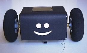
Smiley draws power from the little solar panel on top. His motors are clocks, modified to run considerably faster than normal. The wheels are of a type found on model aircraft landing gears. He feels his way around with 0.3 mm steel wires, bent to form quarter circles.
Smiley's behaviour is based on three rules:
1. If no feeler switches are closed, the motors will obey the `eyes'. Smiley moves towards the best light, while trying to avoid shadow patches.
2. If one of the feelers touches an obstacle, Smiley "follows the wall" in the direction of the better light. Both this and the first behaviour are illustrated here.
3. With both feeler switches closed, the robot will push against one of them, trying to get free.
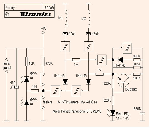
Smiley's heart is the generator built around the schmitt-trigger/inverter and the transistor on the right. When the solar panel doesn't get much light, its voltage drops. The generator reacts by lowering its frequency, causing the average current consumption of the active motor to drop as well. At 2V, the frequency is only 0.5Hz. Smiley moves about very slowly, consuming only 75uA. At 2.2V, the frequency is about 5Hz, giving ten times the speed at more than 600uA. Use clocks that audibly tick and you'll hear Smiley work up enthousiasm as the light gets better
The maximum you want to reach depends on the clocks you find, as the stepping motors inside won't reliably turn clockwise if the frequency exceeds a certain value. My clocks were good up to about 10Hz, giving twenty times the normal speed. With 57mm diameter wheels on the minute hand shafts, that gives Smiley a top speed of about 6 centimeters a minute. Alright, a snail's pace, but you'll definitly see it move.
The single coil, bipolar stepping motors inside the clocks must be driven directly by the Smiley circuit. The modifications are the same as for my original Photovore, and are shown in detail on this page. If you are using different clocks, you will probably need to experiment with different values for the 47uF driver caps and the 390K resistors in the pulse generator. Note that the red LED must have a forward voltage (measured over the LED when it's on) of 1.4V, at least for the clocks shown.
A schmitt-trigger takes input from the feelers and the BPW41 photo diodes. Thanks to the excellent properties of the BPW41 (don't substitute others unless you know what you are doing), the switch from one motor to the other occurs exactly when a line parallel to the wheel shafts points straight at the brightest light, almost regardless of the light intensity. Smiley moves just like my other light-eating `bots. A series of illustrations shows how it works.


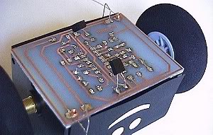
Use double-sided tape to fix the clocks on the PCB. Fit heat-shrinkable tubing over the minute hand shafts and merely push on the wheels - if you are as lucky in finding so good a match
The hood was made of black paper, attached with bits of double-sided tape.
The photodiodes are mounted below the PCB and look downwards at an angle of about 45 degrees. This keeps them out of direct sunlight and makes Smiley move towards better light while trying to avoid shadow patches.
Source: Pyroelectro.com

pyroelectro- C Battery

- Posts : 288
Join date : 2010-11-23
Age : 40
Location : Cebu City
![]()
![]()
![]()
Page 1 of 1
Permissions in this forum:
You cannot reply to topics in this forum|
|
|