
Robotic Arm Gripper
Page 1 of 1
![]()
 Robotic Arm Gripper
![]() by pyroelectro Wed Jun 22, 2011 10:45 pm
by pyroelectro Wed Jun 22, 2011 10:45 pm
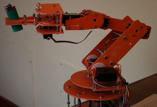
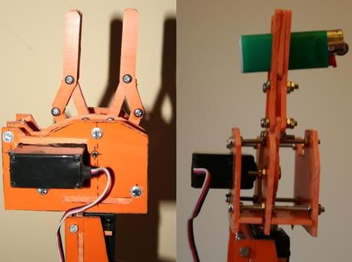
I know that probably the construction of just the gripper of a robot may be useless for everybody but, the method I used to build up the gripper may be really useful to build up the entire robotic arm itself.
Basically I kept the same approach that I used to build the arm, so I used the same PVC material, servos and screws. As result, unfortunately, the arm is actually a little bit heavy and the servos are really under their maximum load so that the two servo at the shoulder can't raise up the arm if it is in extension.
I think that I'll go over this issue installing more powerful servos. The one that I'm using actually are standard 3 Kg/cm torque servos, so I should have great advantages replacing them with 15 Kg/cm ones.
But.....stop chatting and let's see how I did it!
First of all I prepared the base material, the PVC.
I got it from standard sewer pipes, of course new pipes and not used one!

I got some spare pieces of them for free in a construction site but if you can't find any you will surely find them in brico shops. The one I used is about 2-3 mm thick, you will also easily find the grey ones that are thinner (about 1 mm) but they can be used just for few parts of the gripper (the three layer structure) as it is too weak and probably will bend if used for other parts like the finger and the gears.
I cut a small piece of the pipe and then cut it on one side, the I placed it in the home owen! Yes, the one that resides in your kitchen!
After about 10 minutes at about 100 degrees Celsius (but it is bettere to make some test before as probably it will change from different pipes and owens) the PVC was so soft that I was able to get it out an press it beetween two flat wooden boards. This way I got free plastic board ;-)
The second step was drawing the gripper itself. The most annoying part of work like this is to copy the drawing on the PVC board in order to cut it.
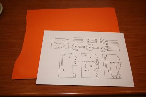
I easily solved printing the pieces drawing with a laser printer and then using the toner properties to transfer it on the PVC board.
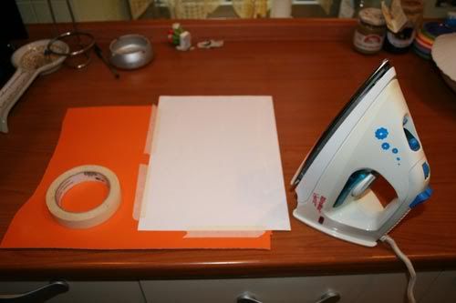
I mean that I simply placed the drawing on the PVC board, with the printed side facing the PVC itself, I firmly blocked the paper sheet with some adhesive tape then I ironed it at the higher temperature and.....voilà! The toner melted transfering to the PVC!

If you don't have a laser printer don't worry! It will work also if you print it out with an ink-jet or whathever other technology and then make a photocopy of it! So, if you would like to try it follow this link to download the gripper scheme that I used.
The third step, probably the longest one, was to drill and cut the PVC board. I used one of the most useful tool that I ever had: the dremel with the cutting disc! I
f you will try this please consider that it will make a lot of dust, PVC powder during the cut, so protect your eyes with pool glasses and your mouth and nose with a good breathing mask.
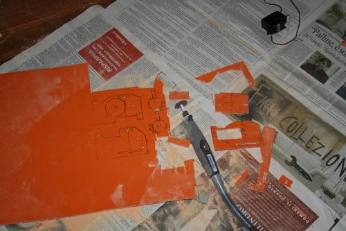
Last step was round down all the pieces in order to have them as precise as possible with a special attention for the gears. This part infact is the most difficult one and I proceeded in very small steps in cutting them.

There's one detail that probably needs some attention: when you transfer the drawing on the PVC board the heat of the iron will probably warp the board. I had this problem on one side of the board itself, and I simply ignored it and cut the PVC anyway, lately I placed the warped pieces on the iron and powered it up again. Then I took the soften pieces and flattened them like I did with the original pipe in the owen. I thought this way was more easy than try to flatten again the whole PVC board instead.
So, after some hours of work (half of a day more or less) I finally assembled my robotic arm gripper!
Source: PyroElectro.com

pyroelectro- C Battery

- Posts : 288
Join date : 2010-11-23
Age : 40
Location : Cebu City
![]()
![]()
![]()
Page 1 of 1
Permissions in this forum:
You cannot reply to topics in this forum|
|
|